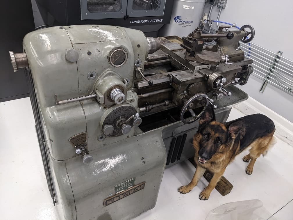
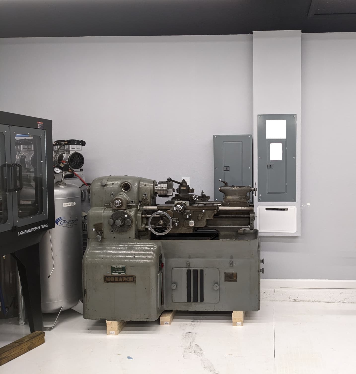
I bought a Monarch 10ee. Here’s the story:
Origin Story
I continously dream of the “perfect” personal shop in my free time.
- What machines would I pick?
- Why would I pick those machines?
- What's the goal?
Going back to lathes, a sensible and drama-free choice for a lathe would be a modern 14x40 lathe. It has core features ready to go. VFD, DRO, E-stops, and more.
Cut a check, and it shows up at my door ready to go. New paint, smooth bearings, and fresh ways. There is zero drama and it's ready to make chips.
Rarely does the sensible choice translate to personal joy.
Here’s my litmus test for purchasing material things.
- Is it timeless? Will I (or someone else) want this 50 years from now?
- Does the machine have a “soul”? What is the incredible backstory that built the brand?
The Monarch 10EE developed during a time when manual machine tools was state of the art. (1920-1970) The Department of Defense poured almost unlimited funds into its development and manufacture.
Below is a YouTube video that explains what went into a Monarch machine tool.
It supported projects like the Manhattan Project. As well as the greater American World War 2 war machine.
 The above image is borrowed from the Shelby County website (opens in a new tab)
This machine tool laid the groundwork for modern-day America.
As time progressed, so did the rest of the world. CNC machines rendered the 10EE, obsolete in the world of high volume production. Fast forward to today. Most manual engine lathes get made overseas and to a price point. Granted, I’ve used modern imported Southbend 14x40 machines, and they work GREAT.
The entire product category of manual machine tools has not progressed, nor do I expect it to.
If you need more capability go CNC. Modern manual engine lathes do their job and do it very well. But, modern import lathes do not have the allure of an unlimited DOD budget machine tool.
A another source of my fascination with the 10EE lies in the aesthetic.
As any product category starts to progress, you will start to see designs start to look VERY similar. Search for a new engine lathe. It all looks the same. Same square headstock, same controls/knobs, same features. Most likely the same suppliers.
No soul.
Look across other matured product categories. Everything looks and feels the same.
- SUVs
- Phones
- Spec Homes
- Sportbike motorcycles
- F1 cars
This happens for a few reasons.
- Engineers and designers copy each other to a convergence point.
- The best solution for the problem tends to be the same
It all gets boring and predictable. Very quickly.
The 10EE aestheic represents the ethos of building the best possible product. With the best technology available at the time. All the while pouring their heart and soul into it.
I love what that stands for.
My lathe is not required to make money, so why stick to the sensible choice? Pick a useful machine that will make you stare at it on a Friday night in the garage while drinking a beer.
That is why I have the Monarch 10EE.
Restoration plan
In 1942, my Monarch 10EE was born. At the time of writing, the machine is 83 years old.
Let that sink in for a second.
The people who built this machine most likely passed away. Their kids are grandparents by now. Every bearing, seal, o-ring, oil passage, and spring is likely as old.
Should you replace everything with new parts? No. If it’s not broken don’t fix it. But replace the parts that will extend the life of the machine and reduce wear.
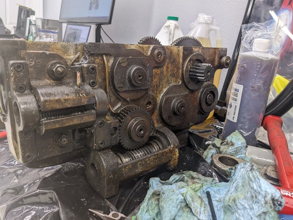
It falls under two categories:
-
All lubricants
-
Carriage oiling system parts
By replacing all those parts, you can ensure that your lathe will enjoy another 83+ years of service life. If skipped, accelerated wear on the ways and spindle bearings may occur.
Here’s lubricant data that I’ve compiled for myself. I used the McMaster Carr generics. It works fine.
| Location Name | Oil Type | Capacity (Quarts) |
|---|---|---|
| Rear Spindle Bearing (Left Side) | Mobil DTE Light (ISO32) | 0.5 |
| Headstock Reservoir (Middle) | Mobil DTE Light (ISO32) | 3 |
| Front Spindle Bearing (Right Side) | Mobil DTE Light (ISO32) | 0.5 |
| Tail Stock Spindle | Mobil DTE Heavy Medium (ISO 68) | 0.2 |
| Tailstock Ways | Mobil DTE Heavy Medium (ISO 68) | 0.1 |
| Apron | Mobil Vactra # 2 Way Oil | 0.5 |
| Gear Box- Reservoir Filling Point | Mobil DTE Heavy Medium (ISO 68) | 1 |
| Speed Reducing Unit (Back Gear) | Mobil DTE Heavy Medium (ISO 68) | 1.5 |
| Main Drive Motor | Mobilux EP2 (NLGI #2) | 0.1 |
| Fluid | Machine QTY (Quarts) | McMaster Part (5 gal) | McMaster Part (Generic Brand:1 Gallon) |
|---|---|---|---|
| Mobil DTE Light (ISO32) (MO-11) | 4 | (opens in a new tab)2158K3 (opens in a new tab) | 3025K25 (opens in a new tab) |
| Mobile DTE Heavy Medium ISO68 (MO-12) | 2.5 | 2158K35 (opens in a new tab) | 3025K34 (opens in a new tab) |
| Mobil Vactra # 2 Way Oil (MO-14) | 0.5 | 2158K41 (opens in a new tab) | 1017K31 (opens in a new tab) |
| Mobil EP2 NLGI #2 (MG-2) | 0.1 | 1416K43 (opens in a new tab) |
Bijur Oiling System Refurbishment
The core work on the refurbishment is to make sure the way oiling system works.
It took some time and space to remove the carriage and all it's subsystems. Once torn down, all oil fittings and lines got purged with air to verify clear passage.
I would not recommend trying to “clean” the existing Bijur metering valves. Those little parts have very small orifices, filters, and check valves. At roughly $20 per valve, replace it. The metering valves under the 10EE apron were all sized to #00.
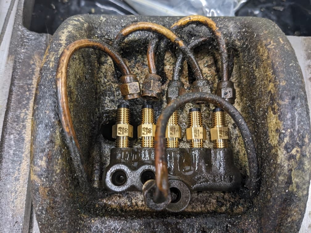
After researching Practical Machinist, it seems that Monarch upsized some metering valves. The large “V” bed way and the large flat way for the Z axis travel had #0 sized metering valves installed. Everything else got sized to the original #00. I followed suit.
Don’t trust any diagrams on the metering valve location to lubrication point mapping. Use an air hose and verify it yourself. My machine was inconsistent with photos found online. Keep in mind the part numbers will change based on the diameter of your oil lines.
While was apron apart, the oil pressure valve got swapped to a 20PSI unit.
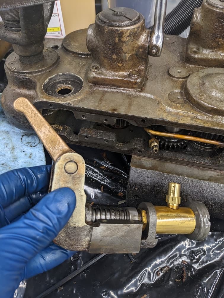
The pump inlet filter also got replaced.
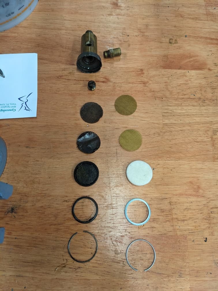
Another note for anyone doing this job. Pre-fill and pre-prime all oil lines before final assembly. The pump moves a VERY small amount of oil per pump.
If the Bijur oiling system got assembled dry and attempts to self-prime. Then the machine might take YEARS of operation before oil hits the sliding surfaces. This is a problem with round dial machines where the oil pump gets driven off the Z-axis handwheel.
I used an automotive brake bleeder/pump to prime the system full of oil. It removed the need to turn Z axis handle a thousand times.
Eventually I want to add a single-shot Bijur oil pump to the spare port of the distribution manifold under the apron. This will allow me to oil the system, without needing to rely on the handwheel. My lathe won't see any production style use, so I don't have too much faith that enough oil will delivered. This a project for a different day.
Square dial machines have the pump spun off the feedscrew. Activating the feed rod and letting the machine run for a while, could prime the system.
I bought all the fittings from FluidLine Systems (opens in a new tab). See below for a table of part numbers.
| Part Number | Bijur Part Description | QTY | Location(s) |
|---|---|---|---|
| B2498 | FJB-3 Metering Unit | 1 | T in Apron |
| B2494 | FJB-00 Meter Unit | 3 | X axis point(s) |
| B2495 | FJB-0 Meter Unit | 2 | Z axis V/Flat Way |
| B4450 | 20 PSI Check Valve | 1 | Pump |
| S175 | LUB G+L Pump Filters | 1 | Pump |
| B6056 | 1/8 Female NPT Adapter | 1 | Used for priming |
| A2835 | 1/8 Male NPT Adapter | 1 | Used for priming |
Single Phase Conversion
Most non-industrial spaces have single phase power and most machine tools require 3 phase power. Hence the need for the conversion. This took the most brainpower to figure out.
There are a handful of ways to do this conversion. I’ve listed them out in THIS (opens in a new tab) Practical Machinist thread. I chose to add a VFD (Variable Frequency Drive) to the existing OEM 3-phase motor.
What is a VFD?
It’s a fancy electrical box that allows 3 phase motors to have variable speed control. As well as soft starting capabilities.
It works by converting an AC power source to DC and then back to AC as the output. The VFD does soft start and rpm control by turning on/off a large switch fast. This creates the general idea of a 3-phase AC sine wave.
When your VFD is sized correctly, it’s possible to power the VFD with a single phase. It will still convert to DC. On the output side, it’s 3 Phase.
VFD Sizing
For the VFD itself, I bought a 10HP Delta MS300 VFD on Ebay for a good price.
I picked a 3-phase 10HP VFD based on this simple math.
OEM 3 Phase Motor: 220 Volts *13.2 Amps = 2904 Watts = 3.8HP Motor
When driving a VFD off a single leg, take the faceplate motor HP and multiply it by 1.7 to derate the VFD for single phase use.
This means I need a 6.4 HP VFD at the least. The nearest nominal 3 PH VFD is 7.5HP. I chose the 10HP VFD. Why? Future-proofing.
At some point, the DC drive may fail. I would like to have the option to remove the DC motor. Create a coupling to the OEM backgear, and attach an inverter grade 3PH 5 HP motor. The future-proof version of the math is 5HP x 1.7= 8.5HP. Upsizing to a nominal VFD size. 10HP.
This logic works now, and over the next 50 years.
Transient voltage spikes
If your motors are VFD compatible (ie inverter-rated), then you would connect the wires from the VFD and move on. Older motors weren’t designed for VFDs and might fail if connected to them. You might be wondering why.
So did I.
Without boring you with the details. A high-frequency on-off signal (square wave input), tends to create transient high-voltage spikes. These spikes can be as high as 1000V depending on the exact system.
Motors that are not designed for a VFD will have thinner winding insulation that works fine for a 240V pure sine wave. But if exposed to 1000V transients, winding insulation will fail and cause the motor to fail. Inverter-grade motors have thicker motor windings to deal with these transient voltage spikes.
What did I do? I added a VFD to the OEM 3 phase motor that is NOT inverter rated. This sounds like a bad idea. But my goal from the VFD is not to vary the RPM, but to convert a single phase input to a 3 phase output.
There are devices on the market called dV/dT(delta Voltage / delta Time) filters. They act as a damper on voltage spikes. If there is a large change in voltage in a short amount of time, then the filter will absorb it. If the input power resembles a 60Hz 240V AC waveform, then it passes through.
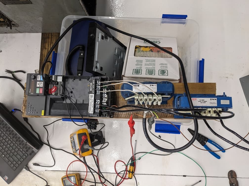
I picked the part numbers for the dV/dT filters by visiting the filter manufacturer's website (opens in a new tab). Then following their technical resources (opens in a new tab) for part sizing. I chose a MTE RL-03501 (input filter) and MTE RL-02502 (output filter) for this application.
I wanted to measure the actual difference in harmonics/voltage spikes. I picked up a Fluke Scopemeter (Oscilloscope). The AC waveforms got measured before/after installing the dv/dt filters. I would measure the actual voltage spikes.
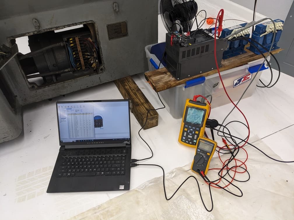
But I’m not an O-Scope wizard, and couldn’t figure out how to read pure voltage spikes with no averaging. Instead I used the software's FFT (Fast Fourier Transform) function. This displays the AC waveform on the frequency domain. A simpler way of saying this. It shows how "pure" is the 60Hz signal.
Here's some graphs that show the difference the dv/dt filters made. Quite a large difference! A perfect filter would have a single bar for the 60hz frequency
Below: The VFD output with NO dv/dt filter
Below: The VFD output WITH dv/dt filter
Alternative motors
If I had a “project” machine with no existing drive/motor system. I would either opt for some flavor of a servo-based system. Such as a Fanuc Redcap or Yaskawa Sigma 7 servos.
Another option is the Technik Clearpath motor line. It’s a motor and drive combined into one compact unit with digital control.
If you fancy it, you can set the controls for a target SFM (Surface Feet per Minute) instead of RPM. This assumes a DRO got integrated into the controls. The machine would vary speed based on tool position. Like a CNC. Pretty cool!
Let's go back to the actual single-phase conversion details.
VFD installation tips
I placed the VFD inside the cubby of the machine under the taper attachment area. There are some holes to allow for ventilation.
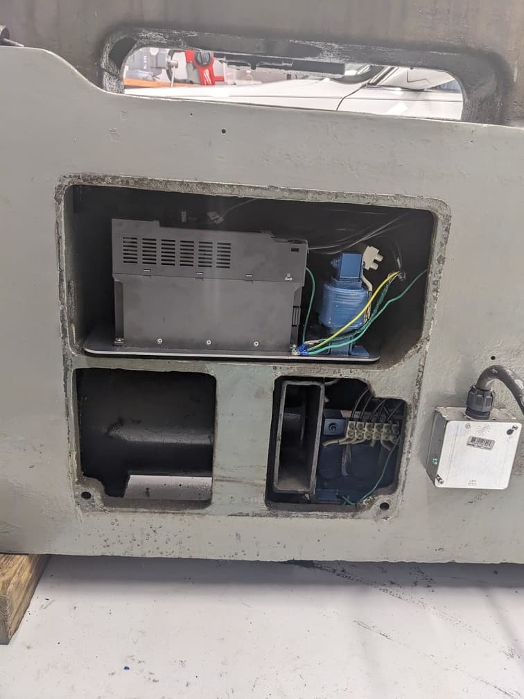
Will I have overheating issues? Not sure, but I don’t think so. The duty cycle on this machine will be so low and so will the heat.
Add all the wires as if you were doing a 3-phase job, but size the conductors for a single-phase load. In the future, if you have access to 3 phase, the machine is easy to wire.
I had to replace the OEM Estop for the motor generator with a conventional latching E-stop. The E-stop got wired to the VFD direct, as well as the OEM “Run” button.
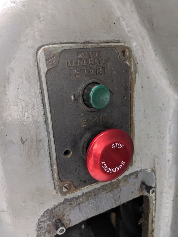
All the controls work OEM-like. Release E stop and click the green button to turn on the motor generator. Perfect. The OEM contactors got removed from the loop. The VFD replaces it's function.
The E-STOP sends stop logic to the VFD. If I need to do a hard electrical kill on the machine. I will use the circuit breaker as a disconnect.
If I wanted to overkill it. I would put another disconnect right at the wall where the machine plugs in. I opted against this since the circuit breaker is a safer location to hard kill the machine if the need occurs.
VFD-rated cable got installed between the VFD and the motor. VFDs output high power and high-frequency signals over a wire. This is also how a radio works. We should be good RF citizens and not interfere with the RF spectrum. VFD cable has shielding to cut RF transmission. Make sure to ground it.
RF testing
If you mess with the RF spectrum, you might get a visit from some 3 lettered federal agencies. I wanted to make sure. So a buddy swang by with his fancy software defined radio, a HackRF (opens in a new tab) to be specific. He did a scan for RF interference between 0-6GHz. We didn't find anything significant. There were a few things non-ideal with our setup, but it gave us rough idea where we stand on RF emissions.
 That’s it for the single-phase conversion via VFD.
Let’s talk about other small things that got done to the machine.
Laser cut Panels
The machine was missing some motor cover panels.
Draw it in CAD. Laser cut via Send cut Send. Done.

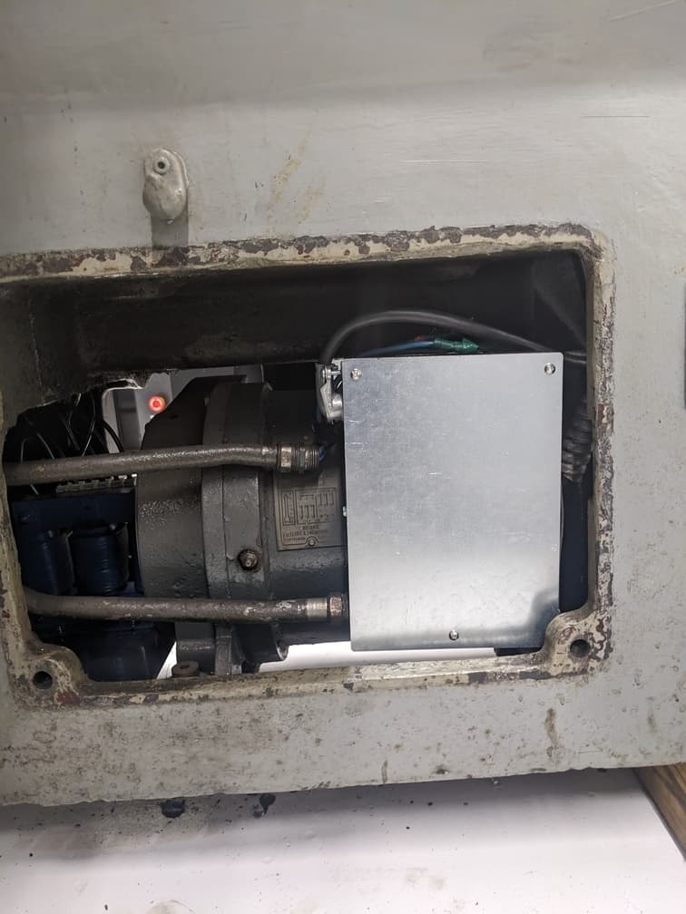
At the same time, I did not want the VFD and the DV/DT filters to sit bare on the machine. It’s unsafe if components can move around relative to each other and don't look clean.
I made a plate to mount those parts. Same thing. Draw in CAD and laser cut via SendCutSend. Add little rubber feet so nothing rattles around. Done.
X-axis Bearing Replacement
While the apron/carriage was being torn down. I noticed that the X-axis lead screw bearing had failed.
Some of the ball bearings got cracked in half. After more investigation, the other half of the bearing assembly was completely missing.
Time to fix this. The ball-bearing assembly might interchange with radial roller thrust bearings. But all the OTS (off-the-shelf) parts on the market are too large.
I couldn’t source a replacement for the bearing, so I made one.
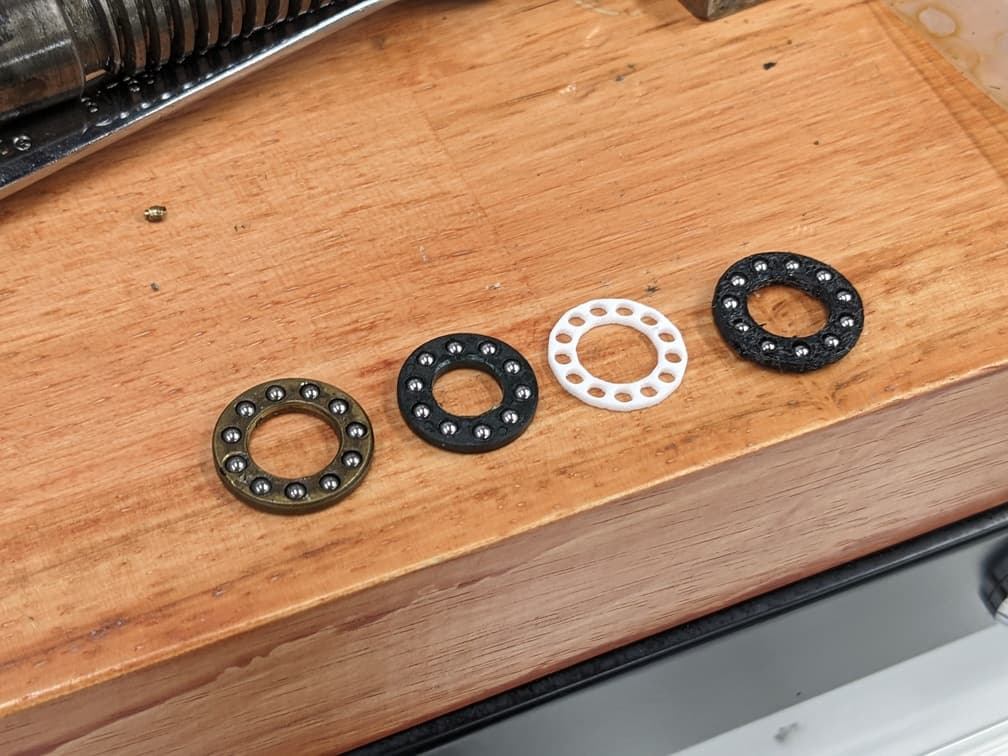
The bearing cage got made in CAD and 3D printed. The steel balls sourced from McMaster Carr.
A castle nut preloads the entire bearing assembly. A Nyloc nut replaced it. This allows the bearing lash to be set, without needing to worry about the castle nut alignment.
Gasket/Felt Wiper Replacements
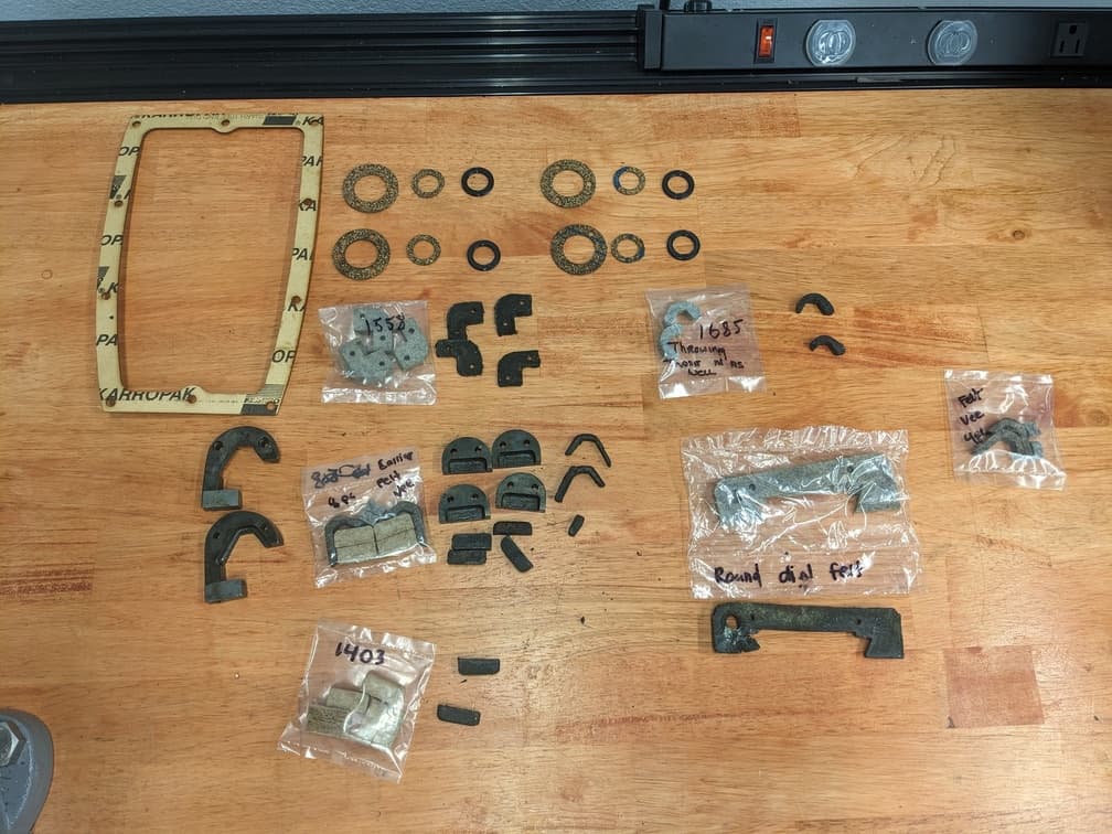
Wipers on a lathe play a very important role for lathes. It keeps chips away from the sliding surfaces, and it keeps oil between the surfaces. Here’s a list of gaskets/wipers that I replaced on the machine.
- Z-axis flat size QTY:2
- Z axis V side QTY: 2
- Carriage Tailstock flat side QTY: 2
- Tail Stock V QTY: 2
- Tailstock Flat QTY: 2
- Taper attachment ways QTY: 4
- Apron Oil Pan Gasket QTY: 1 (Custom)
- X-axis dovetail way QTY: 1
- Headstock top cover gasket QTY: 1
- Apron oil pan gasket QTY: 1 (Custom)
- 6 Sight glasses (Custom)
- 3 on headstock
- Gearbox
- Apron
- Backgear
I also took the liberty of adding a gasket between the X-axis handwheel and the carriage. There is a small hole used to transport oil to the X-axis lead screw. The OEM design has metal/metal, which doesn’t seem like it would seal too well.
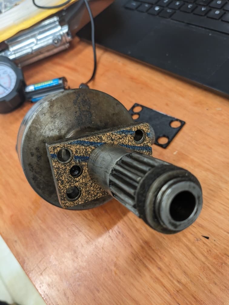
The gaskets and wipers were purchased from the folks at farmboysales.com (opens in a new tab) Great people to deal with.
Custom Gaskets
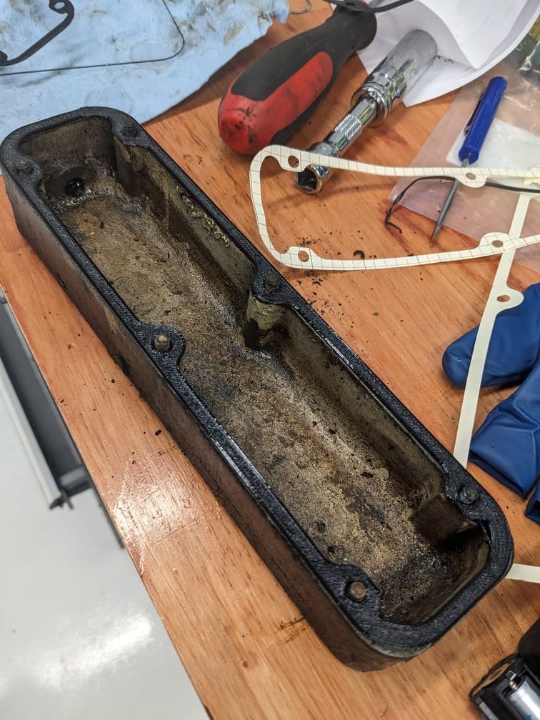
For the custom gaskets, I purchased a cork sheet from the auto parts store, drew in CAD, and cut via a CriCut machine.
You can get a better idea of the process in one my YouTube Shorts.
3D printed parts
Here's a list of other 3D-printed widgets made for the machine.
Replacement Oil Fill Caps
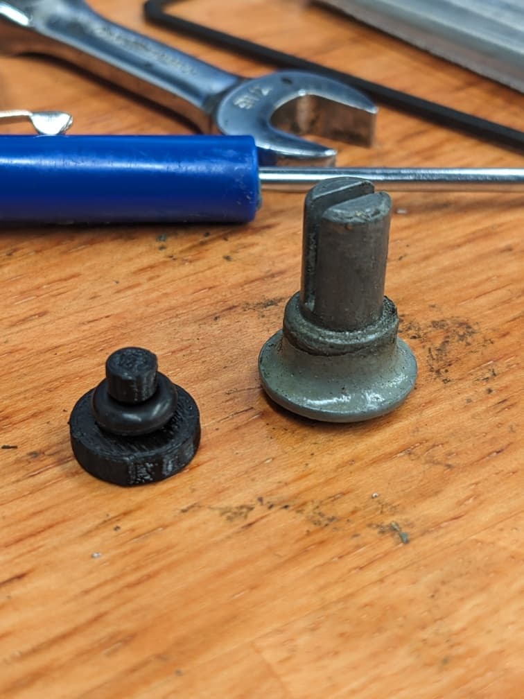
The OEM design doesn’t have a “seal. This means dirt/chips could get in. I 3D printed a new low-profile variant that has provisions for an O-ring.
Oil fill funnel
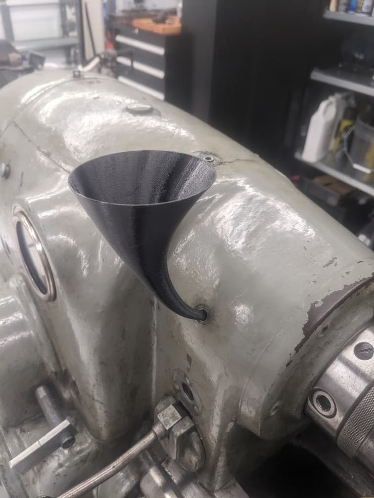
The 10EE has very small oil fill points. A funnel got designed and printed to help pour oil. Works GREAT!
Side cover bracket
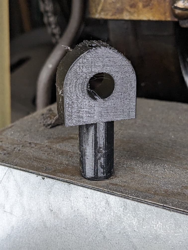
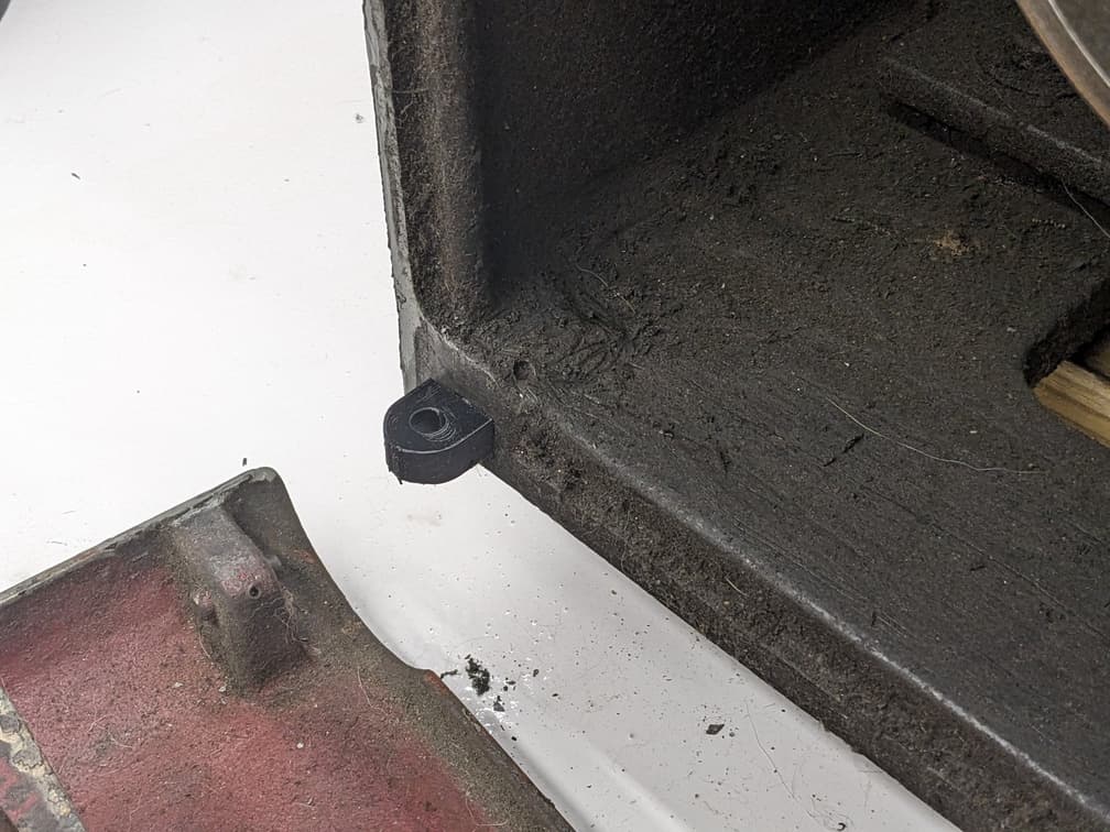
The machine was missing 2 of the mounting bosses for the side cover. The part got made out of PETG plastic, it should be metal. It works for now.
Zerk Grease caps for Lead/Feedscrew
 I got this idea from Cal at Practical Machinist (opens in a new tab). The OEM design doesn’t have a way to lubricate the bearings supporting the lead/feedscrews. Quick CAD and print. Fixed.
Oil glass spacer
 This is used to replace the gasket that is between the machine body and the sight glass
Download CAD Files
All the parts I custom made are avaiable for download on Printables.com (opens in a new tab)
General Machine cleaning tips
As the machine parts were replaced, much time was spent on general cleaning.
I purchased an ultrasonic cleaner for all the small parts. I should have bought this machine YEARS earlier.
It’s great. Greasy parts? Put it in the machine, and it’s CLEAN! Here's a YouTube short I made about it.
Anything that couldn’t fit into the parts cleaner got cleaned with Simple Green.
A coat of wax got applied to all painted and non-oiled surfaces.
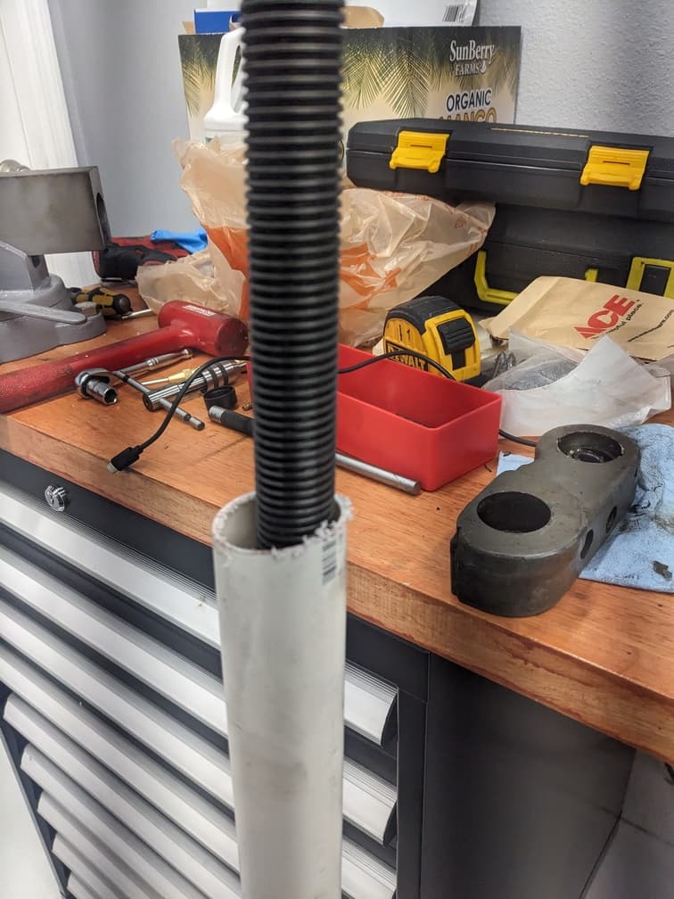
For cleaning the feed/lead screw, I picked up a trick by Grant Gunderson (opens in a new tab) from Garage Journal. The screws got placed inside a PVC tube, and sat in Simple Green / water mix for about a week.
All the grease melted straight off. The parts got coated with Vactra upon removal.
Why didn’t I paint it?
I already had the machine torn down. Why no paint?
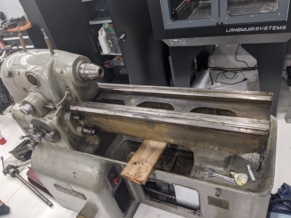
If I paint it, I want to do a proper job. That requires me to strip down the machine to the last bolt, sandblast, and then paint.
I didn’t do this because of space, time, and opportunity cost. I need to spend my time on higher priority things instead of blasting and painting a machine.
Even though I would love to do so.
I’m better off waiting 10-20 years from now. My shop will be much larger and with more capabilities. I’ll hire help to speed things up, and this machine will get every bolt torn down and stripped to bare metal. Ground/Scrapped. The whole 9 yards.
The goal would be a showroom grade machine tool. The 4 Ponds shop 10EE (opens in a new tab) is my reference standard.
Costs
I love keep tracks of costs and being transparent about it. Keep in mind all prices are in 2024 money
| Item | Price |
|---|---|
| Monarch 10ee | 2500 |
| Delta 10HP VFD for Lathe | 246.09 |
| Dv/dt filter | 53.5 |
| DV/dt filter | 82.09 |
| VFD Cable | 25.68 |
| PVC PIpe | 8.75 |
| Electrical Parts | 24.25 |
| Monarch 10ee rigging costs | 776.19 |
| Breakers and bolts | 102.61 |
| Laser cut panels | 142.75 |
| Vactra Oil | 36.05 |
| Oil for gearboxes | 67.52 |
| Boston Gear 17200 | 29.92 |
| Bijur Oil Parts | 209.38 |
| Felt/Gasket Parts | 176.13 |
| Cleaning Supplies | 29.88 |
| Gasket Material | 10.69 |
| Taper Reamer | 10.7 |
| Bearings,Pins,Nuts,Orings | 43.28 |
| Taper Reamer | 14.95 |
| Taper Pin and SHCS Hardware | 24.74 |
| Shapeways 3d print | 27.75 |
| 5C collets 1/16 set Hardinge | 182.79 |
| Bison 3 Jaw chuck | 447.69 |
| Assorted Hardware | 27.36 |
| Total | $5,300.74 |
Planned tooling and upgrades
The goal for this machine is to function as a general purpose machine tool for general prototype lathe work. As a result, the following tooling/upgrades would serve my needs quite well, and "fully tool" the 10EE.
- 2 axis DRO (Newall,Acu-rite or Mitutoyo)
- Auxiliary single-shot oil pump (Bijur)
- Set-Tru 3 Jaw Chuck 6” (Buck) DONE
- 4 Jaw 8” Chuck (Buck)
- 5c Chuck (Atlas or Bison)
- ½” shank Keyless chuck (Jacobs or Albrecht)
- MT2 ER40 collet chuck holder
- MT2 Live Center (Royal)
- MT2 Dead Center (Royal)
- BXA size tooling (Aloris)
- Quick Change Toolpost
- Full set of Maritool Boring bars in boring bar holders
- 80 Degree Turning/Facing Tool
- Part off tool
- Knurling Tool
- Handful of BXA-2 holders for general tooling
- ER40 Collet to MT2 adapter
- Full 5C collet set in 1/64” increments (Hardinge) IN-PROGRESS
- Servo spindle motor (if Motor-Generator fails)
Conclusion
The machine today sits in a refurbished state ready to work for another 20+ years.
I adore this machine and the capability it provides. I would only recommend this machine if you love machine tools and its history. It’s a similar feeling to owning a Ducati.
If you’re looking for “just” a tool to do a “job”. Save yourself the hassle and buy a modern import.
If you want to own and use a piece of history, which also doubles as a useful machine tool. Then Monarch 10EE.
Did you enjoy this website?
Operating at the intersection of mechanical, software and electrical engineering is wildly interesting for me.
These projects can take months to complete, and I'd love to email you when I post new content.
Similar to other personal websites. I will never spam or distribute your email.